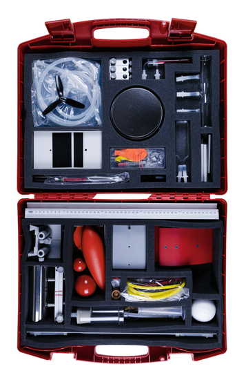
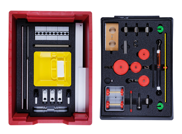
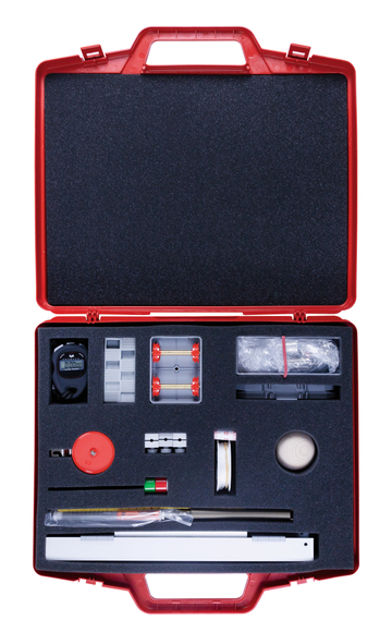
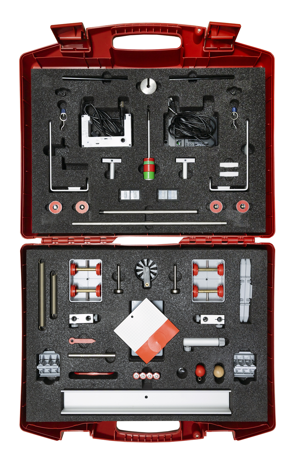
Experiments on Dynamics with PASCO Sensors
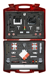
Dynamics Experiment Set 2.0
The high-quality Dynamics Experiment Set 2.0 presents digital data acquisition for curriculum relevant topics in a student-friendly way.
The included PASCO photogates ensure high quality measurement results. With the integrated PASCO sensors, highly precise digital measurements are possible – ideal for investigating velocity, distance, and acceleration.
The experiment set is designed especially for student-led experiments. It is perfectly suited for hands-on experimentation and group presentations and can also be used by teachers for demonstration purposes whenever needed.
Key Features of the Experiment Set
- PASCO Photogates: precise time measurements for reliable data analysis
- PASCO Smart Cart Wheel Encoder: independent measurement of distance, velocity, and acceleration
- Drop Experiment Bag: accurate experiments with small masses
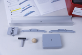
- 1 meter track with scale: ideal for motion and acceleration experiments
A major advantage: The included PASCO photogates do not require an external data logger. They connect via Bluetooth to the freely available PASCO SPARKvue analysis software.


Alignment with Mathematics Curriculum
- Statistics & data analysis
- Functional relationships
- Proportionality
Supporting Materials
The experiment set includes:
- a comprehensive printed teacher’s guide
- editable student worksheets
- step-by-step instructions
- complete sample evaluations
This provides didactically meaningful support for the entire experimental process – from setup to execution and data analysis.
This experiment investigates a motorised trolley moving in a uniform motion on a straight line. For each of the various distances travelled, the corresponding time to cover the distance will be measured in order to determine the speed or velocity of the trolley.
In the first experiment on Newton’s laws, we will investigate the relationships a ~ 1 / m and a ~ F, which will be combined to form Newton’s second law F = m · a at the end.
This involves measuring the acceleration of the trolley directly for each of the various configurations using a spoked wheel on a light barrier. Newton’s first and third laws are covered in experiment D02.2 “Newton’s laws (2)”.
As a continuation to the previous experiment, you will use the following pair of experiments to discover Newton’s first and third laws.
You will observe the principle of inertia and the phenomenon of “action and reaction” with the help of the trolleys on the short rail.
The relationship between distance and time for uniformly accelerating motion is to be investigated by means of an inclined plane. This will involve measuring the time a trolley takes to cover various distances along the plane by means of two light barriers.
Plots of distance against time, velocity against time and acceleration against time are to be obtained for a uniformly accelerating trolley with the help of a spoked wheel passing through a light barrier. The measured curves are then compared to the theoretical ones and interpreted with the help of a game.
With two light barriers and the free fall pocket you can now investigate how the time it takes a body to fall depends on its mass.
The results are then to be compared with calculated values and discussed. Finally the acceleration due to gravity g is measured directly.
Now a light barrier will be used to investigate the relationship between the speed of descent of the free fall pocket vEnd and the height from which it falls h. Initially the relationship between vEnd and h will be derived using the law of conservation of energy for the sum of the potential energy and kinetic energy, then this will be compared to the actual measurement results and discussed.
With the help of two light barriers and the free fall card, you will now investigate how the time it takes an object to fall depends on the height from which it falls.
The results will be compared to the previously introduced law for falling objects and discussed. There is also a supplement which covers the systematic error to which this measurement is subject.
The range, height of trajectory and launch speed are to be measured for a wooden ball launched horizontally from the table top to land on the floor. The launch speed will be calculated from the length of time that the photoelectric beam of the light barrier is interrupted. The measurement results will then be investigated using the previously introduced formula for the range and discussed.
An investigation is to be made of how the period of oscillation of a string pendulum depends on the length of the pendulum, the deflection from the rest point and the mass of the pendulum bob. The period of oscillation of the pendulum will be measured directly using the light barrier.
The period of oscillation of a string pendulum is to be measured directly with a light barrier.
The results should then be used to determine the acceleration due to gravity.
Damping of a string pendulum is to be measured using a light barrier. This should show how kinetic energy decreases exponentially from the lengthening of the time the beam is broken by the pendulum bob as it repeatedly passes through the barrier.
A spring pendulum and a light barrier will be used to show how the measured periods can be used to determine an unknown mass.
For both elastic and inelastic collisions, the velocities of two measurement trolleys along the profile rail track before and after collision are to be measured. The measurements will then be used to investigate whether energy and momentum are conserved in the two types of collision.
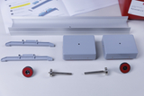
- Pointer
- Profile rail, 1000 mm
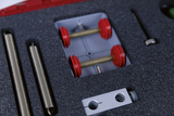
- Self-propelled car
- Weight holder, 10 g
- Slotted mass, 10 g
- Slotted mass, 10 g
- Slotted mass, 50 g
- Tread on spool
- Helical spring, 150 mm, 10 N
- Spring 100 mm / 12 N
- Pendulum ball, wood, 25mm
- Profile rail, 360 mm, with drill hole
- Stand rod, 100 mm
- Wooden ball, 25 mm Ø
- Slotted mass, 50 g
- Clamping tube
- Rings with hook
- Double clamp with slot, aluminium
- AA battery, 1.5 V, alkaline
- Pendulum ball, steel 25mm
- Slotted mass, 100 g
- 4 × Magnet disc on plug
- 2 ×
- 1 ×
- 1 ×
- 1 ×
- 1 ×
- 1 ×
- 2 ×