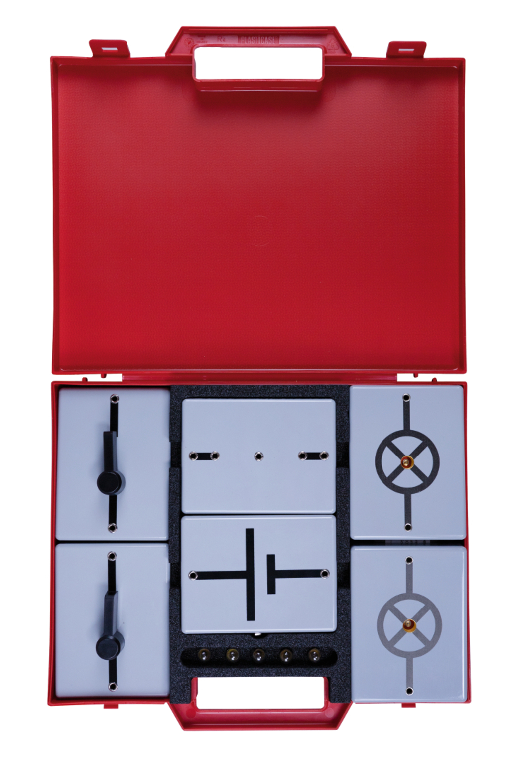
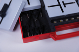
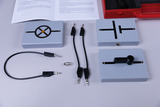
Students kit Electrical circuits for the steel board
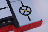
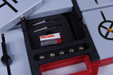
The bases for components are magnetically attachable and the top is printed with the relevant circuit symbol and wiring. They can either be placed horizontally on a bench or
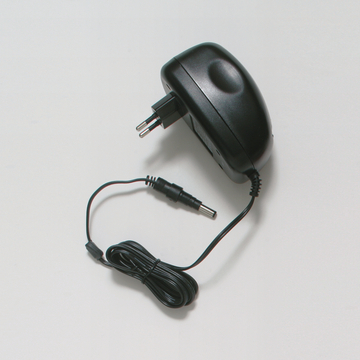
attached vertically to a steel board. The electrical components are mounted inside an open socket but are not visible from above. All the bases are equipped with 4-mm sockets. The power supply component is equipped with a battery compartment for two AA (Mignon) batteries and a low-voltage socket for alternative connection of plug-in power supply 68534.
Detailes instructions for 7 experiments:
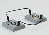
- Simple circuit with lamp
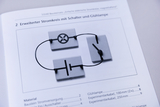
- Circuit with lamp and switch
- Series/Parallel circuit with two lamps
- Electrical conductors and non-conductors
- Logic AND
- Logic OR


Technical specifications
Size of bases: 120 x 90 mm
Size of kit: 330 x 275 x 55 mm
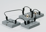
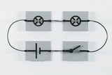
The illumination of the bulb indicates that current is flowing in this electrical circuit.
The students observe the effect on the light bulb with a switch.
One bulb is unscrewed in series from a lamp module and the switch is closed and opened several times. The effect on the other bulb is observed.
An incandescent lamp is unscrewed in parallel from a lamp module and the switch is closed and opened several times. The effect on the other bulb is observed.
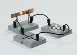
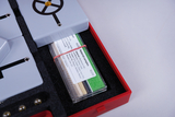
One after the other, different material samples are clamped into the tapping terminals as a connection and the effects on the incandescent lamp are observed.
This experiment can be used to realize the logical function AND, which is a basic function of all electrical and electronic calculating machines.
With this circuit, the simplest form of the logical function OR can be realized, which is a basic function of all electrical and electronic calculating machines.
- Bulb 2,5 V / 0,2 A (10 pcs.)
- 1 × °Material patterns, set of 14 pcs.
- 2 × Plug lead, 25 cm, black
- 4 × Plug lead, 10 cm, black
- Set of 4 Mignon cells, alkaline, 1,5 V
- 1 × Test stand element magnetic adhering
- 2 × Switch element, magnetic adhering
- 1 × Plastic box R4 320x245x50 mm
- 1 ×
- 1 ×
- 1 × Power supply element 3 V,magnetic adhering
- 2 × Bulb holder element MES, magnetic adhering