Demo Set Fundamentals of Physics
Fundamental Experiments in Mechanics, Heat, Optics and Electricity
Use: Demonstration experiments in physics lessons, in the science laboratory or outside a dedicated science room
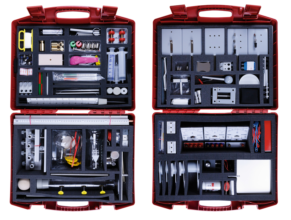
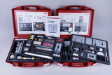
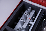
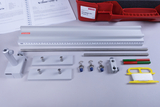
The Demo Set Fundamentals of Physics provides a comprehensive range of experimental materials for 74 experiments covering mechanics, calorics, optics and electricity.
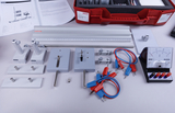
The materials are suitable as basic equipment for science laboratories and can also be used outside a dedicated science room. The set includes a comprehensive illustrated guide with information on experimental setups and hazardous substances, as well as experiment worksheets for all 74 experiments.
With the exception of a simple power supply unit required for the optics and electricity experiments, no additional components are needed to carry out the experiments.

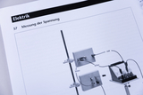


Students measure a friction block between two pointers and determine its edge length from the difference between two scale readings. They calculate the difference between the two scale readings to obtain the object’s edge length directly. They practice defining measurement points, reading scales correctly, and deriving a required length mathematically from two readings.
Students wrap a measuring tape tightly around a beaker and read its circumference at the overlap. The reading where the tape completes one full wrap gives the length of the closed circumference. Students convert a curved measuring path into a linear reading and select a method appropriate to the quantity being measured.
Students fully immerse an object in water, compare two volume readings, and calculate its volume from the difference. The rise in water level corresponds to the volume of the fully immersed object. By calculating V2 − V1, students apply displacement as an indirect method that also works for irregularly shaped objects.
Students allow like magnetic poles to interact freely and observe their non-contact repulsion. The motion of the freely suspended magnets shows that forces can act without direct contact. Students separate observation from explanation and use a magnetic model to interpret repulsion between like poles.
Students load a leaf spring with different masses and compare its deflection. The leaf spring bends farther as the applied mass increases. By varying the load stepwise, students derive a qualitative relationship between pressure force and deformation.
Students load a helical spring step by step and measure its increasing extension. The measured spring lengths show that greater weight produces greater extension. Students build an ordered data series and use it to describe spring extension as an observable effect of tension.
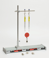
Students zero dynamometers, load them with known masses, and test the proportional force reading. The scale readings rise in the same proportion as the suspended masses, making spring extension usable for force measurement. Students zero an instrument, read force in newtons, and experimentally test the proportional relation between mass and weight.
Students pull a friction block with different loads and surfaces and distinguish static from sliding friction. They find that starting the block requires more force than keeping it sliding, and that load and surface texture affect friction. By varying load and surface deliberately, students distinguish static from sliding friction using their own measurements.
Students pass a cord over a fixed pulley and compare force magnitude and direction. The tension remains essentially unchanged as the dynamometer is guided around the pulley, although its direction changes. Students compare force magnitude and direction and conclude that a fixed pulley redirects force without providing mechanical advantage.
Students load a movable pulley and compare the forces in both supporting cord sections. Both dynamometers indicate about half the weight of the suspended load. Students test symmetrical force sharing quantitatively and explain mechanical advantage in terms of two supporting cord sections.
Students establish several equilibrium states on a first-class lever and compare force and lever arm. For each equilibrium state, they compare force and distance from the pivot and identify equal moments on both sides. Students organize values into force-distance pairs and derive the lever law from several independent equilibrium cases.
Students balance unknown and known masses on a beam scale. At equilibrium, the total masses and therefore the weight forces on the two sides are equal. Students use direct comparison with calibrated masses as a measurement principle for determining an unknown mass.
Students vary the inclination and mass of a carriage and measure the downhill force. The measured downhill force increases both with rail inclination and with additional load. Students vary two factors separately and use the readings to identify each factor’s effect on the force component along the plane.
Students adjust a rail slope until a carriage moves at approximately constant speed. At one particular inclination, downhill force and friction balance so that the carriage rolls uniformly. Students use constant speed as evidence of balanced forces and connect a description of motion with a force model.
Students release a ball on different slopes and compare its increase in speed. The steeper the rail, the more rapidly the ball gains speed. Students compare motions under controlled changes of slope and attribute the stronger acceleration to the greater downhill force.
Students stretch a spring, release it to oscillate, and trace the dissipation of stored energy. After release, the mass oscillates about equilibrium until friction gradually damps the motion. Students trace an energy chain from elastic potential energy through kinetic energy to thermal energy and apply energy conservation.
Students allow two pendulum bodies to collide and observe the transfer of motion. During the collision, the initially stationary body starts moving while the impacting body slows markedly. Students infer energy transfer from motion before and after impact while also considering losses through deformation and friction.
Students roll a ball down an incline, collide it with a block, and trace the energy conversions. A greater release height makes the ball push the friction block farther across the table. Students link gravitational potential energy, kinetic energy, transfer in collision, and frictional heating in a complete qualitative energy account.
Students connect a vessel to a glass tube and compare water levels at different tube heights. The free surfaces remain at the same height in both connected parts even when the glass tube is moved. Students change the geometry while keeping the liquid connection intact and infer the principle of communicating vessels.
Students open outlets at different depths and compare the range and curvature of the water jets. Water from the lower outlet leaves faster and reaches the greatest horizontal distance. Students compare three defined depths and infer increasing lateral pressure from the trajectories of the water jets.
Students immerse a funnel to different depths and measure pressure with a U-tube manometer. The manometer level difference grows as the funnel is immersed deeper. Students use the level difference as an indirect pressure measure and explain hydrostatic pressure by the weight of overlying liquid.
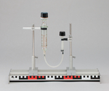
Students connect two water-filled syringes and observe the transfer of volume and motion. When one plunger is pushed, the other rises by the corresponding displaced volume while the water itself is practically incompressible. Students test volume conservation and compressibility and infer how pressure is transmitted through an enclosed liquid.
Students connect syringes of different cross-sections and compare the forces required for lifting. The smaller plunger can raise the larger one against a load with distinctly less force. Students compare piston areas with force effects and derive hydraulic force multiplication together with the associated change in distance.
Students immerse a cylinder, measure its apparent loss of weight, and compare it with the weight of displaced water. On immersion, the dynamometer reading falls by exactly the weight of the displaced water. Students combine force measurement with displaced volume and experimentally verify Archimedes’ principle.
Students measure mass and volume of equal-sized bodies made of different materials and calculate density. Although the bodies have the same volume, their masses and weight forces differ clearly. Students determine mass and volume independently, form their ratio, and interpret density as a characteristic property of a material.
Students vary the pressure above a partly filled diver and observe sinking, suspension, and rising. Higher external pressure forces water into the diver and raises its average density; lower pressure reverses the process. Students explain sinking, suspension, and rising through changing mass or density interacting with approximately constant buoyancy.
Students move the plunger of a connected syringe and observe water being drawn in and expelled. Pulling the plunger out lowers pressure in the syringe and draws in water; pushing it in expels the water again. Students derive the pumping action from pressure differences and transfer the principle to technical suction and force pumps.
Students pull a ring from water and determine the additional force needed to overcome surface tension. Lifting the ring clear of the surface requires considerably more force than its weight alone. Students determine the additional force experimentally and relate it to cohesion between water particles at the surface.
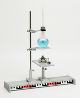
Students warm enclosed air with their hands and track the volume change using a water drop. The warmed air expands and drives the water drop away from the flask along the capillary. Students use drop motion as a qualitative indicator of volume change and infer the relationship between temperature and gas volume.
Students compress air in a sealed syringe and investigate the relationship between pressure and volume. The smaller the trapped air volume becomes, the greater the force required for further compression. Students vary volume deliberately and explain the growing opposing force by rising gas pressure and the subsequent re-expansion.
Students create positive and negative pressure around a balloon and observe its change in shape. Positive pressure compresses the balloon, whereas negative pressure makes it expand visibly. Students change only the external pressure and explain the balloon’s deformation from the pressure difference across its membrane.
Students heat water in a vessel with capillary tubing and use the height change as a temperature indicator. As the water warms, it expands and rises noticeably in the narrow capillary. Students use reproducible liquid expansion as a measurement principle and derive how a liquid thermometer operates.
Students heat water, record the temperature at intervals, and determine its boiling point. Temperature first rises continuously and then remains near 100 °C during boiling despite continued heating. Students construct a time-temperature data series, identify the boiling plateau, and classify boiling point as a characteristic property.
Students reduce the pressure above warm water and observe boiling below 100 °C. Reducing the pressure makes warm water boil again even though its temperature is below 100 °C. Students challenge the idea of a pressure-independent boiling point and explain boiling as a pressure-dependent phase transition.
Students heat and cool a substance and document melting, solidification, and temperature changes. During heating and cooling they observe phase changes together with characteristic sections of the temperature curve. Students assign measured temperatures to physical states and use the curve to describe melting and solidification as reversible transitions.
Students visualize the movement of heated liquid and explain heat transfer by convection. Colored flow patterns show warmer liquid rising while cooler regions sink. Students infer a particle-and-density model from the flow pattern and use it to explain convective heat transfer.
Students heat one end of a metal body and track heat conduction over time. Heating spreads from the hot end along the solid without bulk movement of matter. Students distinguish conduction from convection and explain energy transfer in a solid through interactions between neighboring particles.
Students direct steam so that its energy produces visible motion. The generated steam performs visible mechanical work and sets an object in motion. Students trace the conversion of thermal energy through steam internal energy into mechanical energy and relate it to heat engines.
Die Lernenden erzeugen schmale Lichtbündel und verfolgen deren geradlinigen Verlauf. Die Lichtbündel verlaufen zwischen Quelle und Schirm geradlinig und lassen sich entlang eindeutiger Strahlenbahnen verfolgen. Die Lernenden abstrahieren ihre Beobachtung zum Strahlenmodell und nutzen es, um Lichtwege geometrisch darzustellen und vorherzusagen.
Students illuminate an object from different positions and compare umbra and penumbra. Changing the size and position of the light source produces regions of full and partial shadow. Students construct ray paths and explain umbra and penumbra as geometric consequences of straight-line light propagation.
Students direct light at a plane mirror and compare angles of incidence and reflection. For different incident directions, the angle of incidence equals the angle of reflection. Students compare or measure angles repeatedly and formulate the law of reflection from the resulting pattern.
Students locate the mirror image of an object and compare image and object distance. The virtual image appears as far behind the mirror as the object is in front of it. Students locate an image that cannot be projected and use ray construction to explain image position and mirror symmetry.
Students pass light into a semicircular block and investigate its change of direction at the boundary. At the boundary between air and the optical body, the ray changes direction according to incidence and medium. Students trace rays before and after the boundary and distinguish incidence, refraction, and where applicable total internal reflection.
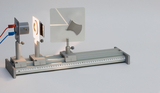
Students form an image with a converging lens on a screen and vary the distances. Different object and lens distances produce real images of different sizes at characteristic positions. Students vary distances systematically, focus real images, and connect the observations with the converging-lens ray model.
Students pass parallel light through a diverging lens and trace the diverging rays. Behind the lens, the rays diverge and can be extended backward to a virtual focal point. Students distinguish real rays from geometric backward extensions and use that construction to describe a diverging lens.
Students produce an inverted image with a pinhole and investigate the effect of distances. An inverted, laterally reversed image appears on the screen, with its size depending on the distances. Students explain image formation using only straight rays through the aperture and transfer the model to a camera.
Students rub a plastic rod with wool and observe electrostatic attraction. After rubbing, the plastic rod attracts light objects and produces electrostatic effects without contact. Students compare the rod before and after rubbing and interpret the observed force as the consequence of charge separation.
Students transfer charge to an electroscope and compare deflections during approach and contact. The electroscope deflection changes characteristically during approach, contact, and charge transfer. Students use the electroscope as a detector and distinguish induction from actual charge transfer through the sequence of observations.
Students combine different electrodes in an electrolyte and measure the resulting voltage. Two different electrodes in an electrolyte generate a measurable electrical voltage. Students compare electrode pairs and infer conversion of chemical into electrical energy as the principle of a galvanic cell.
Students charge an electrochemical cell and then test its voltage output. After charging, the cell can supply a measurable voltage on its own. Students distinguish energy uptake from release and interpret reversible chemical changes as the basis of a rechargeable cell.
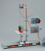
Students deposit copper electrolytically on an electrode and observe material transfer. During current flow, copper is visibly deposited at one electrode while material changes at the other. Students connect current direction with material transport and describe electrolysis as a chemical change driven by electrical energy.
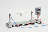
Students pass current through a heating wire and observe its temperature rise. The wire warms while current flows, making the conversion of electrical energy into heat directly visible. Students observe an energy conversion, vary electrical conditions, and relate the effect to heaters and protective devices.
Students build a simple circuit with a switch and investigate open and closed states. The lamp lights only when the circuit is closed; opening the switch interrupts the current path. Students trace the complete conducting path and use a simple circuit model to explain switch operation and current flow.
Students connect two lamps in series and investigate brightness and current path. Both lamps share one current path, so an interruption at one point affects the entire circuit. Students analyze circuit topology and derive characteristic features of series connection from deliberate interruptions or changes.
Students connect two lamps in parallel and investigate independent branches. Each lamp occupies its own branch and can retain a closed current path when the other branch is interrupted. Students compare current paths with a series circuit and explain the functional independence of parallel branches.
Students connect an ammeter in a circuit and measure current. The reading represents the amount of charge passing the series-connected ammeter per unit time. Students choose the correct series connection and polarity of the ammeter and practice safe reading of an electrical quantity.
Students connect a voltmeter in parallel with a component and measure voltage. The parallel-connected meter measures the potential difference between two points in the circuit. Students distinguish voltmeter connection from ammeter connection and assign voltage to a clearly defined pair of points.
Students vary resistance with a potentiometer and record voltage and current. At constant resistance, the measured pairs show a proportional relationship between voltage and current. Students vary an electrical quantity, form or test the quotient U/I, and use measured data to verify Ohm’s law experimentally.
Students measure partial voltages across two series components and compare their sum. Within measurement accuracy, the sum of the partial voltages equals the voltage across the entire series circuit. Students test a quantitative balance rule at several measuring points and justify voltage division in a series circuit.
Students measure voltages in parallel branches and compare them with the source voltage. Each parallel branch has the same measured voltage as the common source. Students compare measuring points systematically and derive the voltage rule for parallel circuits.
Students measure current at several points in a series circuit. Within measurement accuracy, the same current is found at all points of the unbranched circuit. Students test current continuity experimentally and use multiple measurement locations to strengthen their conclusion.
Students measure branch currents in parallel circuits and compare them with total current. The total current splits between the branches and equals the sum of the measured branch currents. Students establish a current balance at a junction and justify the junction rule using their measured values.
Students measure lamp voltage and current and determine electrical power. Using the simultaneously measured voltage and current, they calculate the product U · I. Students combine two measured quantities into a derived quantity and interpret electrical power as energy converted per unit time.
Students heat water electrically, measure time and electrical quantities, and determine the work converted. Using voltage, current, and heating time, they determine the electrical work supplied and compare it with the observed heating. Students construct a quantitative energy balance and assess conversion of electrical energy into heat using their own measurements.
Students place a current-carrying conductor in a magnetic field and observe its deflection. The conductor deflects in the opposite direction when either current direction or magnetic field direction is reversed. Students reverse the two directional variables systematically and derive the direction of magnetic force on an energized conductor.
Students move a magnetic needle around a current-carrying conductor and map field direction. At different positions the magnetic needle points in different directions, revealing the circular field around the conductor. Students map an invisible field from local indicators and connect field direction with current direction in a spatial model.
Students investigate the magnetic field of a coil with a magnetic needle and iron filings. The coil field resembles that of a bar magnet and depends on current, number of turns, and coil geometry. Students compare field indicators and transfer the field-line model from a permanent magnet to a current-carrying coil.
Die Lernenden verstärken die Magnetwirkung einer Spule mit einem Eisenkern und prüfen die Tragkraft. Mit Eisenkern wird die magnetische Wirkung der stromdurchflossenen Spule deutlich stärker und verschwindet weitgehend nach dem Abschalten. Die Lernenden untersuchen den Einfluss des Kernmaterials und erklären den schaltbaren Magneten als technische Nutzung eines stromerzeugten Magnetfelds.
We will shortly provide you with a description of the experiment at this point.
Students reverse current direction and magnet polarity and observe the resulting force direction. The direction of motion depends unambiguously on current direction and magnetic field polarity. Students perform systematic reversals and formulate a rule linking current direction, field direction, and magnetic force.
Students allow a current-carrying coil to rotate in a magnetic field and explain the torque. Opposing forces on the two sides of the coil produce a torque and rotate the coil. Students resolve the rotational effect into individual magnetic forces and explain the operating principle of a moving coil or motor.
Students move a magnet relative to a coil and observe the induced current. The meter responds only while magnetic flux through the coil changes, and the current reverses when the motion reverses. Students distinguish static from changing magnetic fields and identify changing magnetic flux as the condition for electromagnetic induction.
Students vary current in a primary coil and detect the effect in a second coil. Changing current in the first coil briefly produces a measurable voltage or current in the second. Students demonstrate energy transfer without a conducting connection and explain coupling by a time-varying magnetic field.
Students operate two coils on an iron core and compare primary and secondary voltage. The measured voltage ratio depends on the ratio of turns in the two coils. Students compare primary and secondary quantities quantitatively and use induction to explain step-up and step-down transformation.
- 2 × Plug lead 50 cm, red
- 2 × Plug lead 25 cm, blue
- 2 × Plug lead 50 cm, blue
- 1 × Dynamometer, 1 N
- 1 × Dynamometer 5 N
- 1 × Drain vessel
- 1 × Silicone tubing, 7/1,5 mm
- 1 × Stand rod, 500x10 mm dia. stainless steel
- 1 × Magnetic needle 75 mm
- 1 × Rubber stopper for 44660, 60/50 mm
- 1 × Tape measure (10 pcs.)
- 2 ×
- 2 × Electrode, lead
- 1 × Tubular clips, 5 mm
- 1 × Tube coupling
- 1 × Glass tubing, straight, 200 mm
- 1 × Diaphragm and slide holder
- 1 ×
- 2 × Stand rod, 250x10 mm dia. stainless steel
- 1 ×
- 1 × Electrode, zinc
- 1 × Heat protection gauze
- 1 × Bulb, MES, 1,5 V/0,15 A set of 10 pcs.
- 1 × Electrode, copper
- 1 × Slotted mass, 50 g
- 1 × Knife switch on base single pole, single throw
- 1 × Slotted mass, 50 g
- 1 × Voltmeter for students
- 1 × Ammeter for students
- 1 × Galvanometer mV
- 2 × Plug lead 25 cm, red
- 1 ×
- 3 × Double clamp with slot, aluminium
- 2 × Dynamometer, 2 N
- 2 × Syringe, plastic capacity 50 ml
- 1 × Rubber stopper 31/25 mm
- 1 × Rubber stopper 34/28 mm
- 1 × Candles 100x13 mm, 20 pcs
- 1 × Electroscope, isolated on plug
- 1 × Table, small
- 1 × Pair of pointers
- 1 × Scale on board
- 1 × U-tube manometer
- 3 × Rider with clamping tube 75 mm
- 2 ×
- 1 × Surface tension balance
- 1 × Coil for student’s transformer with 600 turns
- 1 × Plug-In Element Base for Three-Pole Elements
- 1 ×
- 1 × Metal axis, 60 mm
- 1 × Bodies for density determination
- 1 × Stand rod, plastic
- 1 × Pulley with hook
- 2 ×
- 1 × Knife switch on base single pole, double throw
- 1 × Lever with bearing and pointer
- 1 × U-core with I-core and clamping screw
- 1 ×
- 1 × Screen, translucent glass, 90 x 90 mm
- 1 × Thermometer -10 to +110 °C
- 1 × Spirit burner, metal
- 2 ×
- 1 ×
- 1 × Copper wire with insulation
- 1 × Heating wire, covered, 0,20 mm Ø
- 1 × Rubber stopper 34/28 mm, 1 hole 8 mm
- 1 × Steel ball, set of 8 pcs.
- 1 ×
- 2 ×
- 1 × Tread on spool
- 1 × Screen and mirror support
- 2 × Magnet rod AlNiCo, one each half painted red and green
- 1 × Stand rod, 100 mm
- 1 × Biconvex lens (converging) f = +100 mm
- 1 × Electrode, carbon with fixing sheet metal
- 1 × Conductor swing
- 2 × Insulating support rod
- 1 × Biconcave lens (diverging) f = -100 mm
- 1 × Screens on rod, projection, metal, painted white/black 150 x 150 mm
- 1 ×
- 1 × Cork powder 10 g
- 1 × Universal mirror, magnetic adhering
- 1 ×
- 1 × Capillary tubing with dial and rubber stopper
- 1 × Needle support on rod
- 1 × Hole diaphragm, 2 mm dia.
- 1 × Diaphragm with arrow
- 5 ×
- 1 × Holding clip on rod, 15 mm
- 1 × Bucket and cylinder
- 1 ×
- 1 ×
- 1 × Pulley, unmounted, 58 mm dia.
- 1 × Rider with clamping tube 30 mm
- 1 × Leaf spring
- 1 × Beaker, Duran, 400ml tall form
- 1 × Erlenmeyer flask, Duran 250 ml
- 1 × Coil for student’s transformer with 1200 turns
- 1 × Friction rubber, wool
- 1 × Moving coil model
- 1 × Caster with iron powder
- 1 × Beaker, DURAN, NF, 100 ml
- 1 × Test tube, 200 x 30 mm
- 3 ×
- 1 × Helical spring, 150 mm, 10 N
- 1 × Bulb, MES, 6,0 V/0,1 A set of 10 pcs.
- 1 × Rings with hook
- 2 × Scale plan, yellow, with bows
- 2 × Lamp holder MES on base
- 2 ×
- 3 ×
- 1 × Syringe, plastic 10 ml
- 1 × Foam insert 2 for 16500, 515x370x100/5 mm (Box1)
- 1 × Foam insert 1 for 16500, 505x355x30/5 mm (Box 2)
- 1 × Foam insert 2 for 16500, 515x370x90/10 mm (Box 2)
- 3 ×
- 1 × Foam insert 1 for 16500, 505x355x30/5 mm (Box 1)
- 1 × Storing diagram,int.vers.(Phys.Demo-Set, kit 1)
- 1 × Storing diagram,int.vers.(Phys.Demo-Set, kit 2)
- 1 × Precision weight, 1g
- 2 × Precision weight, 2g
- 1 × Precision weight, 5g
- 2 × Precision weight, 10g
- 1 × Precision weight, 20g
- 1 × Precision weight, 50g
- 2 × Precision weight, 100g
- 1 × Precision weight, 200g
- 1 × Wooden ball 60 mm Ø
- 1 × Copper tube, 450x10 mm
- 1 × Plastic tubing 200 mm, 3x1 mm
- 1 × Rail support rod for 47001/02
- 1 × Friction block
- 1 × Carriage with rod and piece of mass
- 1 × All purpose rail, 500 mm with scale and bore
- 1 × Condenser with diaphragm and slideholder
- 2 × Bosshead with slit for electrodes
- 1 ×
- Set of 100 rubber rings for soundplates
- 1 × Demo-ruler with block- scale 420 mm and rod
- 1 × Optical model,half cylin-der, magnetic adhering
- 5 ×
- 1 ×
- 1 ×
- 1 ×
- 4 ×
- 1 ×
- 1 ×
- 5 ×