Student Kit Solar Cell
Teach solar energy through hands-on physics experiments
How can sunlight be converted into electrical energy?
With the Student Kit Solar Cell, you can introduce your students to the fundamentals of solar energy through hands-on experiments. The set is designed for grades 5 to 10 and can be easily integrated into physics lessons.
The clearly arranged components enable students to carry out experiments independently in groups and explore how solar cells work in practice. The experiments are designed to be completed within a single lesson.
Only basic student measuring instruments for electrical quantities are required. During seasons with low light levels, an additional suitable light source is needed to illuminate the solar cells. No other accessories are required.

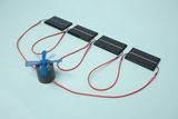
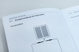
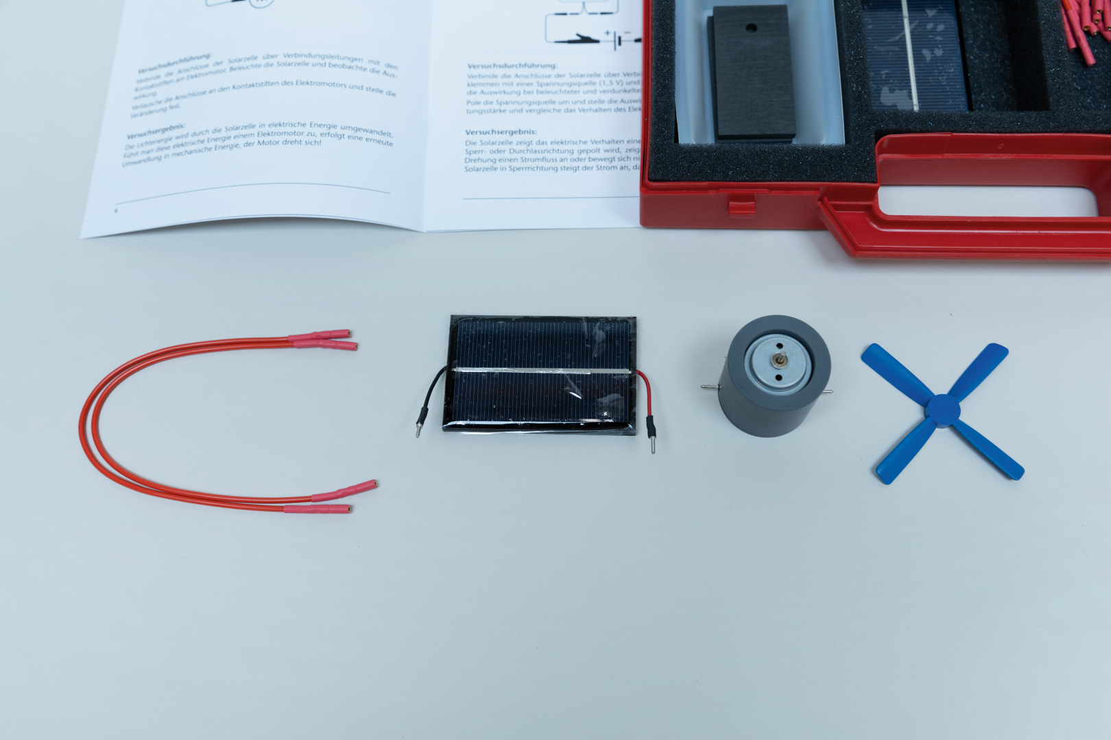
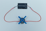


Students connect an illuminated solar cell to an electric motor and observe its rotation. By interchanging the motor connections, they also recognize how the direction of rotation depends on polarity. They trace the conversion of light energy into electrical and then mechanical energy and describe their observations causally.
Students connect a solar cell to a voltage source and an electric motor. They compare its behavior with different polarities and with the solar cell illuminated or shadowed. Using the motor response, they identify the diode effect and explain how greater illuminance in reverse mode affects resistance and current.
Students measure the open-circuit voltage of an illuminated solar cell. They then use carbon electrodes to cover first one half and then three-quarters of the cell surface and record the values in a table. The comparison shows that reducing the active area changes the open-circuit voltage only slightly while students apply a familiar measurement and analysis procedure.
Students determine the short-circuit current of an illuminated solar cell. By covering first one half and then three-quarters of the surface, they systematically vary the active cell area. They record the currents in a table and derive the relationship between illuminated area and short-circuit current from the data.
Students illuminate a solar cell from distances of 10, 20, and 30 cm. At each distance, they measure both open-circuit voltage and short-circuit current and compare the quantities in a table. The data reveal different dependencies: voltage changes only slightly, while short-circuit current increases with illuminance; students identify and explain this relationship.
Students illuminate a solar cell from angles of 90°, 45°, and 20° while keeping the distance constant. They measure and compare the short-circuit current for each orientation. They identify perpendicular incidence as the most effective orientation and apply the relationship between angle of incidence and output to the positioning of solar modules.
Students measure the solar cell’s open-circuit voltage and short-circuit current at three distances from the light source. They calculate internal resistance from each pair of values and record voltage, current, and resistance together. They apply a mathematical analysis procedure to measured data and show quantitatively that internal resistance rises as illuminance decreases.
Students connect two, three, and four solar cells in series and measure the open-circuit voltage in each case. They compare the values with the voltage of one cell and record the results in a table. From these data, they develop a simple model of voltage addition and use it to predict total voltage under uniform illumination.
Students connect four solar cells in series and attach an LED with the correct polarity. With sufficient illumination, the series connection provides the voltage required to light the LED. Using this technical application, they trace the conversion of solar energy into electrical energy and then light and transfer the principle to lighting beyond direct sunlight.
Students first measure the short-circuit current of one solar cell at a distance of 20 cm from the light source. They then connect two equally illuminated cells in parallel and determine the changed current. From the comparison, they infer that the parallel connection increases the effective area and short-circuit current while open-circuit voltage remains constant.
Students connect four solar cells as two series pairs and then connect the pairs in parallel. They use the combined circuit to power an electric motor and vary the distance from the light source. They determine how series and parallel connections jointly provide voltage and current for greater usable power and apply this model to the construction of a solar module.
Students connect six solar cells in series and attach them to two carbon electrodes in a sodium chloride solution. During exposure to sunlight, they observe gas bubbles at one electrode as visible evidence of chemical change. The setup links photovoltaic electricity generation with electrolysis and enables students to distinguish clearly between experimental observation and interpretation.
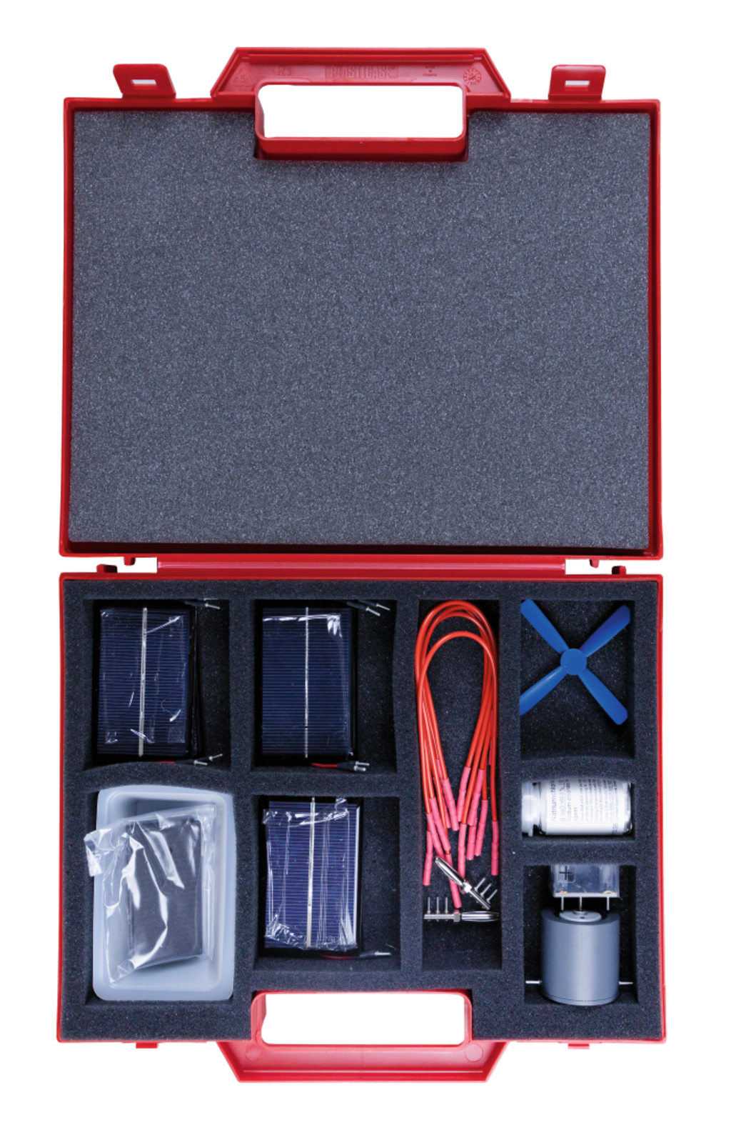
- 6 × Solar cell
- 1 ×
- 1 ×
- 1 ×
- 1 × LED
- 1 ×
- 1 × Electric motor with propeller in block
- 1 × Lidfoam R3, grey 260x200x10 mm
- 2 ×
- 7 ×
- 2 ×